Specification
MODBUS APPLICATION PROTOCOL SPECIFICATION
See also:
Modbus Data model
There are two types of data:
- discrete: single bit, can represent a single on/off state
- analog: multiple bits 16, 32, etc that can represent a number (10, 53, -1002, 232.32)
Analog values can be divided into two categories:
- integers: no decimal values (1, 23, -23, 232)
- floats: has decimal values (12.0, 151.232, -2912.23)
Integers can be divided into signed and unsigned values:
- signed: can have negative values (23, -123)
- unsigned: can only be positive values (12, 0, 982)
Integers can also be 16 or 32 bit. The number of bits determines the maximum value that can be represented:
- uint16: unsigned 16-bit (positive only) integer (range: 0 to 65535)
- int16: signed 16-bit (negative or positive) integer (range: -32767 to 32767)
- uint32: unsigned 32-bit integer (range: 0 to 4,294,967,295)
- int32: signed 32-bit integer (range: -2,147,483,647 to 2,147,483,647)
All numbers in a computer are represented as binary bits (0’s or 1’s). Humans typically represent numbers in decimal (base-10), but when working with computers, we sometimes also use hexadecimal (base-16). To think about the different bases:
- Binary (base-2): like counting with 2 fingers
- Decimal (base-10): like counting with 10 fingers (what most of us are used to)
- Hexadecimal (base-16): like counting with 16 fingers. Hex numbers are usually have a 0x preceding them, or a ‘h’ following (0x23, 4500h).
To convert between the different bases, see the following example. There are various calculators that can convert between dec and hex as well, which is needed for larger numbers.
| Binary (base 2) | Decimal (base 10) | Hexidecimal (base 16) |
|---|---|---|
| 00000 | 0 | 0x0 |
| 00001 | 1 | 0x1 |
| 00010 | 2 | 0x2 |
| 00011 | 3 | 0x3 |
| 00100 | 4 | 0x4 |
| 00101 | 5 | 0x5 |
| 00110 | 6 | 0x6 |
| 00111 | 7 | 0x7 |
| 01000 | 8 | 0x8 |
| 01001 | 9 | 0x9 |
| 01010 | 10 | 0xA |
| 01011 | 11 | 0xB |
| 01100 | 12 | 0xC |
| 01101 | 13 | 0xD |
| 01110 | 14 | 0xE |
| 01111 | 15 | 0xF |
| 10000 | 16 | 0x10 |
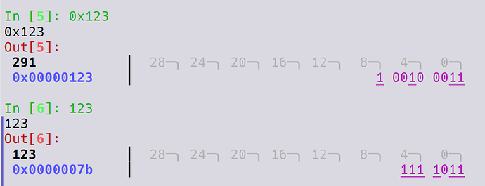
One might ask – why use hexadecimal, when humans have 10 fingers? The reason is that each hexadecimal digit maps exactly to 4-bits, so when working with computer registers it is much more straightforward to think about register values in hexadecimal. In the below example we map both 0x123 (hex) and 123 (dec) to bits. The hex value maps nicely to 3 groups of 4-bits. With the dec number, you need to convert the entire number to visualize the bits.
Transports
- RTU: RS485
- supported serial port setup: 9600N81 (9600 baud, no parity, 8 bits, 1 stop bit)
- TCP: Ethernet
| Characteristic | RTU | TCP |
|---|---|---|
| Physical Layer | RS485 (4-wires) | Ethernet |
| Speed | Slow | Fast |
| Distance | 1000m | 100m |
| Configuration | Baud rate, parity, bits, stop bits | IP address |
| Topology | Single client | Multiple clients |
| Used in | Simple sensors, meters, simple PLCs | PLCs, HMIs, advanced controllers |
Modbus TCP Configuration
The gateway and the device both need to have an IP address assigned to them. If there are no other devices on the network, then static IP addresses will need to be assigned to both devices. The following are suggested:
- Gateway:
10.0.0.1 - Device:
10.0.0.2
When entering Modbus registers in a component, the device address along with the standard Modbus port (502) should be used in the URI field:
10.0.0.2:502
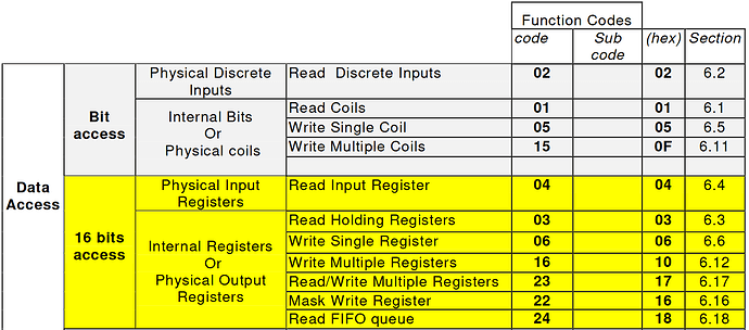
Function codes
Each Modbus operation has a function code, which defines what type of data we are operating on, and if we are reading or writing the data.
Function codes typically map as follows:
- 01 → coil
- 02 → discrete input
- 03 → holding register
- 04 → input register
- 05 → coil
- 06 → holding register
Modbus addresses
Modbus address can be specified in two ways:
- Coil/Register Numbers. Encode the registers/coil type in the address.
- Data Address (what is used on the wire) and the function code is specified separately.
Standard Coil/Register numbers
| Coil/Register Numbers | Data Addresses | Type | Table Name |
|---|---|---|---|
| 1-9999 | 0000 to 270E | Read-Write | Discrete Output Coils |
| 10001-19999 | 0000 to 270E | Read-Only | Discrete Input Contacts |
| 30001-39999 | 0000 to 270E | Read-Only | Analog Input Registers |
| 40001-49999 | 0000 to 270E | Read-Write | Analog Output Holding Registers |
Converting from register numbers to addresses
The biggest challenge in setting up Modbus is figuring out if the datasheet specifies register number or address. If the numbers match up with the above table, then it might be a number. But this is not conclusive, as the address range of 0 to 0xffff can give you addresses from 0 to 65,535, so its very possible to have a input register with address 40,100, which might look like a holding register. In many cases, some experimentation is required to determine what the address numbers mean.
If you are given register numbers, then you must subtract an offset 1, 10001, 30001 or 40001 (depends on the type) to get the address.
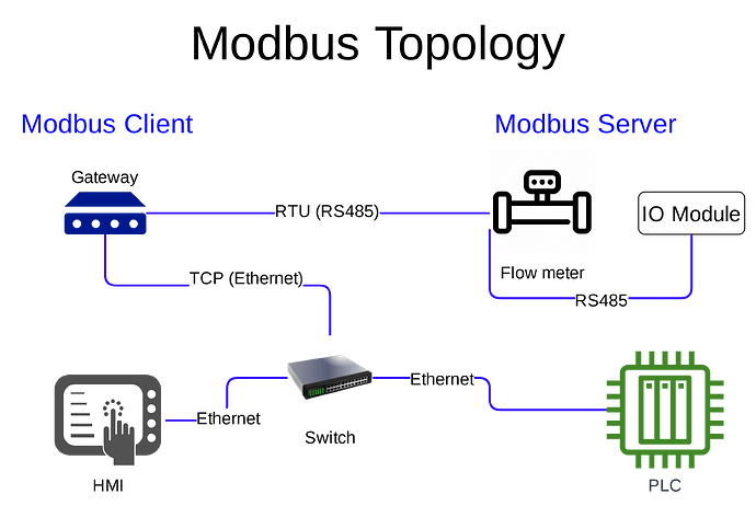
Modbus Topology
The image below shows how Modbus RTU and TCP connections can be made. Some of the differences include:
- RTU connections can be daisychained
- TCP connections require a switch, and multiple clients can talk to a single device (server) using TCP. With RTU, you can only have a single client (gateway, HMI, etc) on the bus.


