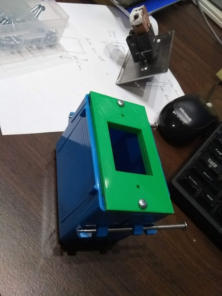
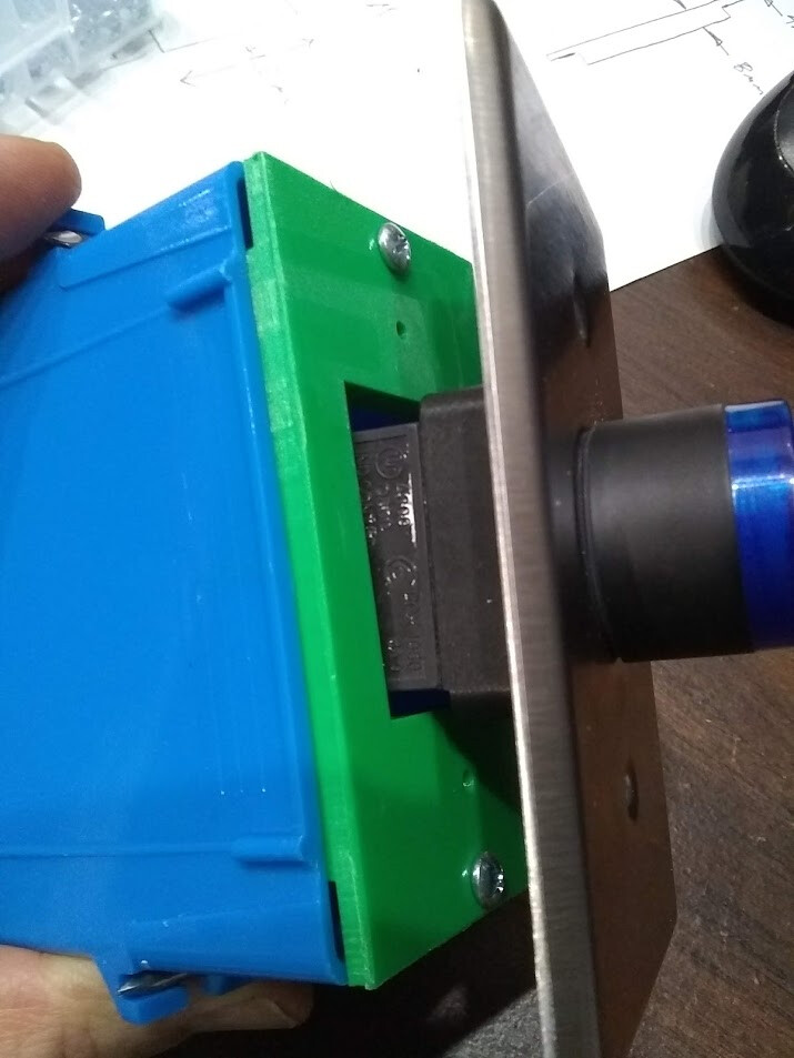
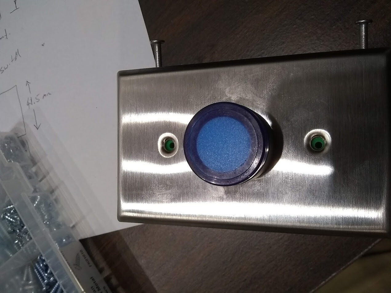
I recently needed an adapter for a stainless button faceplate as the holes did not line up with a standard 1-gang electrical box. After hearing good things about FreeCAD, I decided to give it a try for creating the model – it is an amazing tool. FreeCAD is an open-source parametric 3D modeler. The basic process for creating a part is:
- create a 2D sketch
- draw rough shapes (lines, rectangles, circles, etc). These shapes do not need to be to scale as they will be constrained later to the correct size/shape.
- add constraints until the 2D shape is fully constrained
- extrude (pad), revolve, sweep, etc. the 2D sketch into a 3D object.
- repeat until the part is completed
The constraints in FreeCad are very intriguing. This allows you to specify drawing information that is convenient (dimensions you might have on hand, etc). Below is an example of a 2D sketch for this part:

For the holes, the space between the holes on a 1-gang box was measured and then entered as a constraint. A symmetry constraint with respect to the origin was also added, and a constraint that one of the holes had to be on the Y axis. With these three constraints, the holes were fully located. If this distance needed adjusted in the future, changing a single number (parameter) is all that is needed to tweak the model.
As you work in FreeCAD, a tree of objects and operations is built up. The parameters in this tree can be changed at any time and the model re-generated. Trees are very useful data structures – you’ll find them in many projects (Git, SimpleIoT, Blockchain technologies, etc).
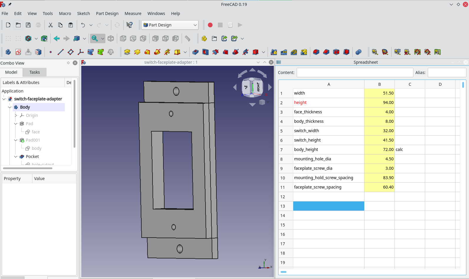
FreeCAD lets you enter data in a spreadsheet and then use that data in the design parameters. In the example below, if you change any of the dimensions in the spreadsheet, the model updates automatically. Excel like formulas can even be used in the spreadsheet cells for calculated values.
The following video has a lot of good information about using spreadsheets for constraints:

3D printing can be accomplished by exporting the design to a *.stl file. One important detail I learned is you need to select the last object in the part body, and export that to a STL file; otherwise, negative attributes like holes may be missing. FreeCAD builds up the model by successively applying operations, so if you export the last one, this ensures everything has been run. See the FAQ for more information.
Cura was used to do the slicing and the design was then printed on a Tevo Tarantula printer. This part turned out very well.